=======MEASURING LED INTENSITY TO TRACK LED DEGRADATION
Kenneth A. Miller and
Nasir J. Zaidi, Spectra Light Laboratories,
Burbank,
CA.
(818) 954-9222
Abstract
Empirical data
indicates that the light output of Light Emitting Diodes (LEDs), such as
those used in traffic control light modules, degrades over time. An ITE
interim purchasing specification mandates LED traffic signal module
manufacturers verify minimum performance for at least three years, but field
testing demonstrates significant dimming in two years or less. Further, this
gradual dimming presents a potential safety hazard. The solution: a novel,
portable, calibrated photometer (light meter) for field testing LED traffic
signal modules during routine maintenance.
Back to Top ^
The Requirements
?The manufacturer
shall make available a process to test compliance of minimum intensity
values in a controlled and independent laboratory during anytime in the
warranty period. Alternately, the manufacturer shall make available a
portable, calibrated light meter to allow for field measurement of luminous
intensity of LED signal modules.?
Specifications for
traffic signal lights used in the
United States have been
established in standards from the Institute of Transportation Engineers (ITE).
The above is quoted from Publication Number ST-0017A, Equipment and
Material Standards of the ITE, Chapter 2a, Section 4.3 of the ITE
Interim Purchase Specification for LED Vehicle Signal Modules (Vehicle
Traffic Controls Signal Heads Part 2).
Further, Section 7.2.2
states: ?LED signal modules which exhibit luminous intensities less than the
minimum values specified in Section 4.1.1 within the first 36 months of the
date of delivery shall be replaced or repaired.?
The foregoing
requirements mandate that manufacturers have the responsibility of verifying
minimum intensity output anytime within the first three years following
installation of their LED Vehicle Signal Modules. The specification allows
the manufacturers two options to verify compliance: 1) pull the module out
of the field and send it to an independent testing laboratory; or 2) provide
a portable, calibrated light meter (photometer) for field measurement of
intensity.
But a versatile, field
photometer must also readily accommodate a myriad of evolving standards.
Several jurisdictions--for example, Caltrans in
California,
the Oregon Department of Transportation, and the cities of Philadelphia, PA
and Davis, CA--have already developed their own standards for LED traffic
signals (Wyland, 1996; Suozzo, 1998). ITE specifications are only
recommendations: It is up to local jurisdictions to accept, modify or reject
the ITE specification (Bullough, 2002).
Back to Top ^
Causes of LED Degradation
The primary failure
mechanism of conventional incandescent-lamped traffic signals is the
catastrophic breaking of the lamp filament, immediately ending light output.
However, the primary failure mode of LED-lamped traffic signals is not so
obvious. Rather, it is a continuous, gradual degradation in light output
over time. This subtle degradation eventually results in a potential safety
issue (Hutchinson,
2001).
Since any one signal
color is ?on? for 50% of the time or less, signal lights may operate for
five to ten years or more before completely burning out. Without accurate
field measurement instrumentation, maintenance personnel would be oblivious
to the safety hazard caused by a degraded signal light level, and traffic
engineers would not know when to replace a critically dim LED module. A
traffic accident may result, for example, if the visibility of a dim red
?stop? signal is impaired in a bright sun situation.
What causes
degradation? High ambient temperature is the primary culprit (Hochstein,
1998), but design, installation site power, materials, humidity and time are
also important factors. Oxygenation of aluminum in the LED junction,
corrosion of the many module electrical connections, aging of the electrical
drive circuits, dirt accumulation on the module lens, or deterioration of
the module lens, such as pitting, warping, fading or the like--are some
additional reasons for field degradation.
Empirical data indicate
that LED lamp life decreases exponentially with operating temperature. In
other words, as operating temperature gradually increases, overall lamp
light output decreases at an increasing rate. These changes are gradual, but
at some point, the light output level will no longer comply with the
required minimum. And eventually, the light level will be so low that
visibility may be impaired.
While room temperature
(25?C.) lifetimes may in fact approach one hundred thousand hours, operation
at close to 90?C. may reduce LED light life to less than seven thousand
hours. Actual data collected in solar heating studies of traffic signals
show that internal temperatures approaching 85?C. may be rather common in
the U.S. Southwest for at least a significant part of the day. This is
particularly true if amber and green incandescent lamps are retained, since
the heat from incandescent lamps greatly increases the temperature
surrounding the LED light module (Hochstein, 1998).
Back to Top ^
Impact of LED Degradation
The ITE addresses the
ambient temperature issue in Technical Note #3: Operating
Temperature
Range
and the Impact of Environmental Conditions.
Obviously, of paramount concern are installations where high ambient
temperatures are the norm.
To overcome this
problem, some manufacturers increase the initial light output by turning up
the LED electrical drive current (Grossman, 2000). If light output is
initially set higher, then minimum performance can be guaranteed for a
longer period of time. However, driving the devices harder raises the device
junction temperature, further accelerating the rate of light output
degradation, particularly in high ambient temperature environments. Other
manufacturers have included photo sensors within their modules to detect
degradation. But that is not the same as measuring the actual light output
passes through the lens to the viewer.
Also, as the device?s
junction temperature increases, its color (dominant wavelength) shifts
slightly toward the long wave, or infrared end of the visible optical
spectrum. This is a particular problem for the safety-critical red LED
signal light module. As the color shifts to deeper red hues, the visibility
of the light decreases rapidly, since the daylight-adapted human eye
spectral response (called 'Photopic' or 'CIE 2? Standard Observer') falls
off quickly (Figure 1: Typical Spectral Responses) in the red portion of the
visible spectrum. In other words, the slope of the human eye?s spectral
response to visible light drops dramatically in the red LED region,
partially offsetting the gain from higher drive currents.
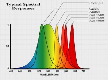
Figure 1: Typical
Spectral Responses
Back to Top ^
Spectral Mismatch
Spectral response, or
sensitivity to light as a function of wavelength, is a fundamental parameter
for light measurement instruments. Photographic light meters, whose spectral
response is optimized for photographic film, cannot be used to accurately
measure LED signal lamp intensities.
Instruments designed to
measure optical light output must see light ?like the human eye sees light?.
Called photometers, these instruments must be specifically calibrated in the
narrow spectral regions where LED traffic modules emit light?whose peak
outputs are approximately 505-565nm (green), 590-595nm (amber), and, most
critically, 620-660nm (red) (Figure 1: Typical Spectral Responses). The
typical photometer, however, is calibrated against a ?white light?
incandescent standard source, and may possess significant spectral mismatch
errors in the red region.
Silicon cells, the most
often used type of detectors, exhibit a spectral response vastly different
from the human visibility function (Figure 1: Typical Spectral Responses).
Since silicon cell spectral response rises in the red portion of the visible
light spectrum, a shift toward the infrared causes an increased signal from
a silicon detector. However, the signal from a detector that has been
filtered to the human visibility curve, is decreased by the same spectral
shift.
Back to Top ^
Criteria for a
Calibrated LED Field Photometer
As a first requirement,
the instrument must be portable. That is, it must be easily transported to
the installation site, and easily operated in a routine traffic signal
maintenance environment. A stable, reliable, and easy-to-use, hand-held
apparatus is highly preferable.
As a second
requirement, the instrument should have the versatility to be calibrated to
meet current and anticipated LED traffic signal intensity measurement
standards.
Back to Top ^
The Optical Radiation Family
In general, all optical
radiation, whether ultraviolet, visible or infrared, is quantified in three
domains--spectral, spatial and temporal.
In the human visible
spectrum, the spectral domain relates to the ?color? of the optical
radiation. It is the sum of light?s radiometric emission values modified by
the human response to color, as a function of wavelength. For LEDs, which
are predominantly spectrally pure, or highly saturated sources, dominant
wavelength and color coordinates are the specified color parameters. For
highly saturated sources, such as LEDs, a laboratory device called a
spectroradiometer is the preferred measurement instrument. The
spectroradiometer measures the spectral power distribution (spd) of light
sources and uses a computer to determine the various photometric and
colorimetric parameters.
The primary criterion,
in the spectral domain, is that the field photometer be well-calibrated to
the human visibility (Photopic) function in the regions that correspond to
the spectral emission of LED traffic light modules. (Color measurement is
not required in the field.)
Is the optical emission
concentrated in a narrow beam or broadcast over a wide angle? The spatial
domain relates to the geometric angle of light emission, and also the
instrument?s collection angle. An instrument called a goniometer, designed
to measure light output as a function of angle, is the instrument used in
the laboratory. (Goniometric measurement is not a field requirement.)
Individual LEDs in a
module are primarily beam-type emitters. That is, the light they emit is
highly directional, not at all like incandescent lamps that are visible over
a wide viewing angle. To overcome the narrow viewing problem, some LED
module manufacturers have opted for using several hundreds of LEDs, while
others spread the optical beam with highly sophisticated, computer-designed
lenses.
Back to Top ^
Measurement Parameters
For round traffic
signals, axial luminous intensity (candelas) is the measured parameter. For
other traffic control devices, such as turn arrows and pedestrian control
signals, luminance value (photometric brightness, in candelas per square
meter) is the specified parameter.
Luminous intensity
(candelas, cd) is measured with an illuminance photometer. This device is
calibrated to measure the density of visible light flux (in lumens) falling
on its optical collector, usually a translucent disk or hemisphere.
Intensity is then
calculated via the inverse square law. Luminous intensity (candelas) of a
spatially uniform emitting source equals: the measured illuminance; times
the square of the distance between the source, and the plane of the optical
collector.
In the English system,
if a source that is one foot away from a perpendicular optical collector
measures 1.0 footcandles on a calibrated illuminance photometer, then the
source is 1.0 candelas. [The illuminance metric (S.I.) unit is the ?lux?,
and the distance is expressed in meters.] (To convert: 1.0 fc = 10.76 lux,
or 1.0 lux = 0.929 fc.)
Luminance is the
parameter usually specified for traffic control lights that do not have the
spatially uniform emission of round traffic signals?such as turn arrows and
pedestrian control signals and other icons. In the laboratory, luminance is
usually measured with a ?spot photometer?, an optical instrument with a
narrow collection angle that is typically 1?.
Luminance is a measure
of the average ?photometric brightness? of a surface. The typical English
unit is the ?footlambert? (fl), and ?candelas per square meter? (cd/m?) is
the metric (S.I.) unit. (To convert: 1.0 fl = 3.426 cd/m?, or 1.0 cd/m? =
0.2919 fl.)
The luminous intensity
(candelas) of spatially non-uniform emitters is more difficult to ascertain,
since it is necessary to both measure the luminance and also precisely know
the area of emission. To avoid the complication of having to know the area
of emission, icon light levels are usually specified only in luminance units
(cd/m?), and not in candelas. [The luminous intensity (in cd): is the
luminance value (in cd/m?); times the area of emission (in m?). (The ?m??
term cancels, leaving ?cd?.)]
Back to Top ^
Ambient Light
Shields/Optical Collectors
Laboratory photometers
used to measure discrete LEDs are generally supplied with a light shield
tube (LED Receptor) that is precisely one foot long (or a specified fraction
of a meter). The Receptor tube provides several benefits. By precisely
fixing the distance between the emitter and optical collector, the light
shield tube both defines the instrument?s collection angle, and provides a
convenient means to convert from units of illuminance to intensity units.
And, the tube also it eliminates stray light, a potential major source of
measurement error.
But a simple tube is
not the solution for a field instrument. In the field, in bright sunlight,
with large array emitters, the problem is much more complex. To prevent the
unwanted inclusion of ambient light in the measurement, ambient light
shields must be customized for both 8? and 12? signal lights, and also for
pedestrian and other traffic control signals.
Besides eliminating
extraneous ambient light, the shields must also contain an optical collector
within: fixed at a precise, repeatable distance from the module lens.
Together, the shield-plus-optical collectors define the photometer?s optical
collection geometry, its spatial domain criterion.
Therefore, a variety of
easily interchangeable ambient light shields/optical collectors are
necessary for field use, and the photometer must be individually calibrated
for each shield.
Finally, the temporal
domain describes whether the emission is d.c.-powered, or a.c.-powered
(steady-state or pulsed), and over which frequencies. Since most traffic
control devices in the
United States
operate in a 60Hz environment, high frequency photometer response is not
required. For the temporal domain criterion, the field photometer usually
needs to accurately measure only to twice the 60Hz frequency (120Hz).
Back to Top ^
The Spectra? Candela II Traffic Signal Light (TSL) Field Tester System
Figure 2: TSL Field
Tester System
To meet the specified
requirements, Spectra Light Laboratories developed the Spectra? Candela II
TSL Field Tester System (patent pending) (Figure 2: TSL Field Tester
System). The hand-held, battery-powered photometer with LCD readout and
optional memory storage, incorporates interchangeable light shields/optical
collectors (called Light Integrators). Calibrated Light Integrators are
available for 8? and 12? round traffic signal lights, and other traffic
control lights, such as turn arrows. Independently calibrated,
switch-selectable Red, Yellow and Green LED channels accurately quantify
visible LED light output and record degradation. Compare readings to
specified values to verify pass/fail. And the system is supplied in a
high-impact field case for convenient storage and easy transportation.
Back to Top ^
TSL Operating Procedure
To use, proceed as
follows, after performing routine signal module lens cleaning.
1) Press the ?On/Off?
button and verify that the LCD does not indicate ?LOW BATT?.
2) Install the black
?Zeroing Disk? via the ?quick disconnect? spring-loaded bayonet mount. Press
the ?On/Off? button again and verify that the instrument ?zeros?.
Figure 3: TSL Field
Tester with Light Integrator
3) Select the
appropriate Light Integrator shield/collector (for example, 8? or 12?, round
or arrow) and attach the shield to the photometer head via the bayonet mount
(Figure 3: TSL Field Tester with Light Integrator).
4) Check/set the
?units? and ?mode, switches. Then set the ?selector? switch to the channel
corresponding to the signal light type, size and color.
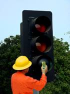
Figure 4: Field
Measurement
5) Place the light
shield flush against the corresponding light module lens (Figure 4: Field
Measurement).
6) Press the ?On/Off?,
button for a few seconds to measure. The reading is displayed for 60 seconds
on the LCD.
7) Compare the Tester?s
reading to the attached reference chart to determine pass or fail.
Back to Top ^
Conclusion
Although ultimate
failure of LED traffic control modules may take many years, light intensity
degradation is continuous and subtle. Degradation varies as a function of
each module manufacturer?s design and the environment in which the module is
installed.
Field maintenance
personnel and traffic engineers now have a calibrated, portable instrument
available to them to accurately quantify traffic signal module light output
intensity. If the level falls below minimum performance criteria, the module
must be replaced. If the module is still under warranty, it can be returned
to the manufacturer. And if maintenance personnel maintain accurate records,
a history can be developed and used to predict when specific classes of
signal modules might have to be replaced.
The periodic recording
of LED signal light intensities, acquired during regularly scheduled
maintenance, verifies minimum light output performance and eliminates the
traffic safety hazard caused by intensity degradation.
Back to Top ^
References
Bullough, John, K. H.
Huang and K. Conway 2002. Optimizing the Design and Use of Light-Emitting
Diodes for Visually Critical Applications in Transportation and
Architecture, Lighting Research Center Website, School of Architecture,
Rensselaer Polytechnic Institute.
Troy,
NY.
Grossman, Hyman issued
Nov. 28, 2000.
United States
Patent Number: 6,153,985.
Hochstein, Peter A.
issued July 21, 1998. Heat Dissipating L.E.D. Traffic Light,
United States
Patent Number: 5,782,555.
Hutchison, Michael C.
issued Feb. 9, 1993. Electronically Steerable Light Output Viewing Angles
for Traffic Signals,
United States
Patent Number: 6,323,781 B1.
Institute of
Transportation Engineers (ITE) 1997. Publication Number ST-0017A, Vehicle
Traffic Control Signal Heads, Part 2: Light Emitting Diode (LED) Vehicle
Traffic Control Signal Modules, An Interim Purchase Specification, VTCSH
Part 2: LED Vehicle Signal Modules (Interim), Chapter 2a.
Suozzo, M. 1998. A
Market Transformation
Opportunity
Assessment for LED Traffic Signals.
Washington, DC: American Council for and Energy-Efficient Economy.
Wyland, M. 1996. Update
on LED traffic light technology. Energy Investments, Inc.
Back to Top ^
|

 ===
===